- Whatsapp: +8615825688470
- Email: [email protected]


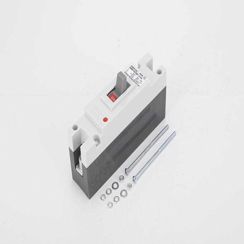
As DC power becomes more prevalent in applications like photovoltaics, electric vehicles, and energy storage, protecting these systems is critical for safety and reliability. A DC molded case circuit breaker (MCCB) is an essential component, but its proper installation is vital. Unlike AC circuits, DC circuits are more difficult to protect due to the continuous nature of the current, which makes extinguishing an electrical arc much harder. A mccb circuit breaker is the backbone of these safety systems.
This guide provides a detailed look at how to properly install, troubleshoot, and maintain a mccb for dc application to ensure the safety and longevity of your system.
Choosing the right breaker for your system is the first step. While both AC and DC breakers serve the same basic purpose of protecting circuits from overcurrent, their design and operation differ significantly due to the nature of the current they handle.
| Type | Current Characteristics | Difficulty in Extinguishing Arc | Safety Risk |
| AC Circuit Breaker | Current fluctuates periodically | Easier to extinguish | Relatively low |
| DC Circuit Breaker | Continuous, non-interrupted current | Difficult to extinguish | Higher, requires special design |
Because DC current is continuous, a DC arc doesn’t have a “zero-crossing” point to help it extinguish naturally. This means DC MCCB breakers must be specifically designed with arc-extinguishing capabilities to quickly and safely interrupt the circuit. Using an AC breaker in a DC system can be extremely dangerous and lead to equipment damage or fire.
Proper preparation is key to a safe installation. Before you begin, gather the right tools and personal protective equipment.
| Tool Category | Essential Tool | Function Description | Selection Warning |
| Testing Tools | Multimeter (DC Range) | Verifies the circuit’s zero voltage status | AC multimeters may give inaccurate readings when testing DC circuits. |
| Insulation Resistance Tester | Tests the cable’s insulation strength (≥10 MΩ) | Environmental factors like humidity can affect results. | |
| Installation Tools | Torque Wrench (0.5–25 N·m range) | Ensures precise control over terminal pressure | Over-torquing can cause thread deformation. |
| Infrared Thermographic Camera | Pre-checks for potential overheating at contact points | Relying on tactile checks may miss hidden hazards. | |
| Protective Gear | 1000V Insulating Gloves | Protects against DC arc penetration | Standard AC gloves may not be rated for DC systems. |
Proper installation of a dc mccb involves meticulous attention to detail on both the power supply and the load side.
The wiring at the power supply end directly affects the breaker’s protection efficiency. Follow these steps carefully:
Connecting the load side correctly is vital for protecting your equipment from surges and other faults.
Even with a perfect installation, issues can arise. Knowing how to identify and address them quickly is essential.
| Fault | Cause | Emergency SOP | Preventive Tech |
| Failure to Trip | Oxidized contacts / Jammed mechanism | Cut upstream power and monitor with an infrared camera. | Perform monthly “stroke tests” to check mechanism precision. |
| False Tripping | EMI / Overcurrent setting drift | Use an oscilloscope to capture current ripple. | Install EMI ferrites and set an appropriate hysteresis for the trip settings. |
| Contact Welding | Insufficient breaking capacity | Do not attempt to reset. Replace the breaker. | Monitor the (let-through energy) value in real-time. |
| Dielectric Breakdown | Electrochemical corrosion / Condensation | Use a megohmmeter to test for low insulation resistance (<5 MΩ). | Maintain a humidity-controlled environment for your DC circuit breaker panel. |
Improper installation can lead to significant safety hazards and property damage. Here are a few typical issues:
| Fault Type | Physical Manifestation | System-Level Consequences |
| Contact Melting | High-temperature deformation at the breaker connection points, copper busbar erosion | Equipment failure, power supply interruption |
| Fire Risk | Electric arcs igniting insulation materials or surrounding combustible objects | Fire accidents, facility damage |
| Equipment Short-Circuit Damage | Abnormal current surges damaging sensitive components at the backend | Inverter/Battery Management System failure |
Regular maintenance is the most effective way to prevent failures. A tiered approach ensures long-term reliability.
Proper installation and maintenance of DC MCCB breakers are paramount for safety and reliability in DC power systems. By understanding the key differences between AC and DC breakers, carefully following installation steps, and performing regular maintenance, you can protect your equipment and prevent potential hazards like fires or system failure. A well-maintained dc circuit breaker box is crucial for this. As DC technology advances, new breakers with remote monitoring and smart management will make these systems even more reliable, but a solid foundation in proper installation and care will always be the most important factor.
WEBSITE&YUEQING NUOMAKE TECHNOLOGY CO.,LTD.
Privacy Policy | SiteMap
Copyright NUOMAK
 Optimized by Seraphinite Accelerator